Collecting Digital Images
Light Box with Full-Spectrum Fluorescent Bulbs
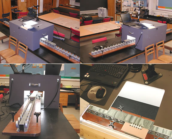
Rollers pass cores through the light box for successive image collection. The box has a camera port on the top and has been painted on the inside with flat (non-gloss) white paint. Inside there are eight 2-ft full spectrum fluorescent bulbs to illuminate the cores.

Clockwise from top left: Front view right side.; Front view left side.; View in top of box through access doors and camera port.; View in end of box showing core roller system. The scale is set up on a brick even with the core surface on its right side. Click on image for large version (~148 KB JPEG).
Collecting Digital Images
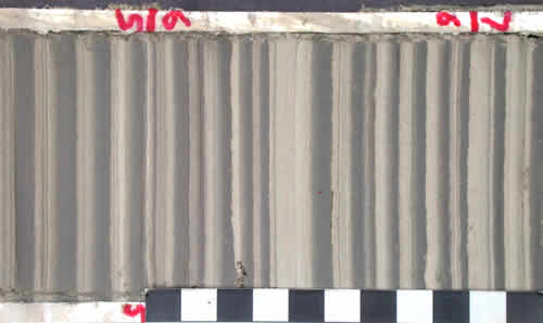
An example image is shown below. Some suggestions and hints:
- All digital images should be collected at a high resolution and must include a scale. As explained below copied sets of digital images with their resolution changed in a program like Photoshop can be used if a particular program needs images of a lower resolution.
- We recommend that full spectrum bulbs be used to illuminate the core when images are collected.
- Cores should be partially and evenly dried to accentuate the contrast between layers of different grain size (see Core Preparation page).
- Images are generally collected with the long axis of the core parallel to the long (horizontal) dimension of the images and with the bottom of the core section on the left side of the image. Our computer measurement program will automatically rotate the images to vertical on the computer screen.
- Bedding in the varve sequence should be lined up, as much as is possible, so that it is parallel to the shorter dimension of the image.
All images must have a scale as standard practice. Computer programs using the images have calibration routines that take advantage of scale bars on the images. The scale bar should be placed along the side of the image perpendicular to bedding. If you are collecting images specifically for gray-scale profile analysis it may be convenient to have the scale parallel to bedding across the bottom of the core section.
If images are going to be used in a computer measurement program a marking system should be developed, such as marks placed on the core liners, which show the bottom of the first varve that will be measured on an image and the top of the last varve to be measured on an image. The mark for the top of the last varve will appear as the bottom of the first varve to be measured on the next image and so on in a sequence of core images.

High resolution image of varves from Kelsey Ferguson brick yard, Redland Brick Co., East Windsor, Conn. Up is to the right. Scale is in cm. Starting and ending marks for computerized varve measurement are indicated on the core liner in red ink.


